

Autumn Update 2025
- Oct 10, 2025
- 3 min read
John Dunn is progressing well with the machining of the cylinders. What follows
is a series of images showing the remaining work on the bolting face of the
castings, starting with the holes for fixing the exhaust manifold being drilled and
tapped. This is followed by one showing all the holes drilled for bolting the
cylinder to the frames. In order to provide a suitable seat for the bolt heads on the
outer face of the casting, these locations have all been spot faced, as can be seen
in the next illustration. With the machining of both cylinders taken to this stage,
they are shown together, in readiness for setting up for the next operation, which
is the machining of the bores


The first photograph, which illustrates this next operation, is a general view of the
casting set up on the borer with the boring bar, which is supported at both ends, in
position through the cylinder casting. Next is a closer view of the other end of the
cylinder with the cutting tool shown in position in the boring bar, prior to the
commencement of machining. This is followed by the first cuts to the bore being
made, then a view of the finished pass to obtain the required size of the bore.


Having completed the machining of the main cylinder bore to finished size, before
moving away from this area, the bell mouth at the end of the bore and the face for
attaching the cylinder cover were addressed. Also shown in these next views is the
machining of the bore for the valve spindle neck ring and gland, plus the face
which incorporates the studs for the valve spindle glands.
Photographs of the setup and machining of the cylinder castings have been kindly
provided by John Dunn Engineering. More of these and his other work, can be
viewed on his Facebook page, plus a short video of some of the machining
operations as detailed above.


Above show two images of one of the front cylinder covers for
GOWRIE, set up in one of the lathes at our workshop. The first shows the initial
setup before the commencement of machining, whilst the second shows the
completed machining of the inside face. The intention is that these covers will be
machined, but not drilled for the fixing studs, as this process will be carried out at
John Dunn Engineering at the same time as the main castings are drilled and
tapped for the studs.
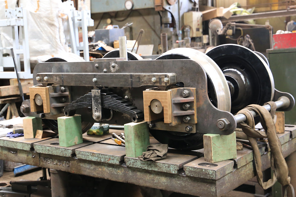
We finish this section with several photographs showing three views of progress
on the trailing bogie, which is now reaching the final stages of its construction and
assembly. In the first, the spring and equalising beam are in position, followed by
two views with the stirrups connecting the ends of the spring to the equalising
beam in place.
On the final page are two views of the current state of painting on the tanks, cab
and bunker, which have now received, as well as two coats of grey primer, two
more coats of undercoat in readiness for the top coat to be applied, but it will be
some time before this can be done, as there is still considerable work required,
which will entail the removal of these structures from the frames in order for more
items to be attached to the carrier frames. This cannot be achieved whilst the tanks
and bunker are in position.


Comments